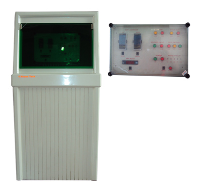
Evaporator Chlorine evaporator with water as heat transfer medium Multitube heat exchanger
1. Technical Data
| 1.1 General Data | ||||||||||
|---|---|---|---|---|---|---|---|---|---|---|
| Evaporation capacity and media |
|
|||||||||
| Inlet connection | Groove flange ANSI 25 (G 1") according to ANSI B16.5 class 300 rating | |||||||||
| Outlet connection | Tongue flange ANSI 25 (G 1") according to ANSI B16.5 class 300 rating | |||||||||
| Weight with heat transfer medium | approx. 220 kg incl. control unit and load unit | |||||||||
| Weight of control unit | approx. 18 kg | |||||||||
| Max. operation pressure | 11 bar with bursting disc 14 bar (standard version) 12,5 bar with bursting disc 16 bar |
|||||||||
| Permissible ambient temperature | 0 to +40 °C | |||||||||
| 1.2 Materials | |
|---|---|
| Enclosure | GFK |
| Parts in contact with media | Steel, stainless steel, silver, copper, brass, bronze |
| 1.3 Electrical Data | |||||||||||
|---|---|---|---|---|---|---|---|---|---|---|---|
| Power consumption |
|
||||||||||
| Heating elements |
|
||||||||||
| Circulation pump*** |
|
||||||||||
| degree of protection control unit | IP 66 | ||||||||||
| Contact load of outputs | Max. 250 V, max. 50 VA ohm resistive load | ||||||||||
| Input voltage control signals | Floating contacts (24V DC / max 5W per input) | ||||||||||
| NOTE: The type plate can be found on the back of the instrument support. | |||||||||||
| 1.4 Control Panels: Control Unit and Load Unit | ||||||||
|---|---|---|---|---|---|---|---|---|
| Dimensions | 400 x 600 x 200 mm | |||||||
| load unit |
|
|||||||
| control unit |
|
|||||||
| load unit 400 200 600 550 350 M8 ca. 240 | ||||||||
2. Installation
2.1 Transport and Storage
Handle with care, do not throw!
Dry storage place.
The gas connections must be tightly closed during transport and storage!
WARNING If humidity penetrates the device: Danger of corrosion with chlorine gas!
2.2 Unpacking
Observe when unpacking:
No humidity should get into gas-leading parts!
No foreign matter should get into gas-leading parts!
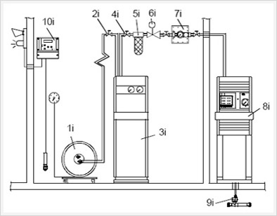
2.3 Installation Example

1. Gas container or container battery
2. Shut-off valve at the inlet side
3. Evaporator RV 171W
4. Shut-off valve at the outlet side
5. Liquid trap and filter
6. Pressure reducing valve
7. Vacuum regulator
8. Gas dosing unit
9. Injector
10. Gas warning device

