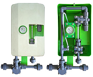
The New model MK- I is semi automatic gas type. Vacuum operated Solution feed Chlorinator designed to provide a continues & measured quantity of gas while in operation. It is suitable for use with chlorine. Sulphur dioxide or ammonia gas. Intermittent “Stop-Start”. Control or automatic “Shut-Off”. Can be achieved by interruption of the motive water supply. The Instrument is arranged for wall fixing & incorporates a gas tilter with flush mounted vacuum gauge to indicate the vacuum of the ejector entering the chlorinator a vacuum controller a variable area flow meter with integral control valve: an injector assembly with non-return valve & interchangeable nozzle & throat & a manifold mounted pressure gauge indicating the pressure of the operating water.
Design
CONTROL : The vacuum control system will maintain the capacity selected.
ACCURACY : Meters are calibrated to give an accuracy of better than 40% of the maximum indicated gas flow.
CALIBRATION : With the modern variable area flow meter incorporated in this instrument substantial linear results are achieved on the calibrated scale.
RELIABILITY : The materials chosen for the construction of the instrument have been carefully selected for the duties which they are to perform extensive use has been made of modern plastic materials which are highly resistant to attack by the gases. Where metals have been used advantage has been taken of modern metallurgy techniques to withstand the corrosive action of the gases handled.
ACESSIBILITY : Removal of the cabinet shroud exposes all components for easy maintenance. In restricted areas the unique construction of the instrument enables it to be easily lifted its wall fixing & taken to a bench foe overhaul purposes. Removal of the front panel only requires the disconnection of four unions.
SAFETY : Due to the nature of the gases metered to this equipment prime consideration has been given to the safety of the operating personnel. The system incorporates a positive shut-off in the event of water failure a pressure relief to avoid gas “Build-up” & a vacuum relief to cover gas failure or chokage.
FLEXIBILITY : The capacity of the instrument can be readily changed by simply removing the existing meter tube & scale & inserting replacements of the desired range. Under some circumstances if may also be necessary to change the injector nozzle & throat combination to suit the new conditions.
MAINTENANCE : The simplicity of design & robustness of all components reduce maintenance to an absolute minimum. Under normal operating conditions an annual examination of the instrument & the renewal of certain joint rings & gaskets is all that would be necessary.
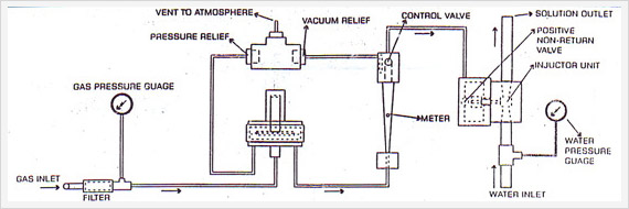
DIAGRAM A :
Vent to atmosphere
Vacuum relief valve
Pressure relief valve
Gas pressure gauge
Water pressure gauge
Operating water pressure inlet connector
Injector & non-return valve assembly
Gas inlet connection
Solution outlet connection
Gas filter
Meter
Gas control valve
Vacuum controller.
Construction
CABINET : Two-tone fiber-glass “lift-off” shroud for easy access.
FILTER : Silvered metal with renewable glass wool insert.
GAS GAUGE : Bourdon tube with silver ABS / PVC / PTI diaphragm oil filled capsule dual-calibrated.
VACUUM CONTROLLER : Plastic ABS / PVC / PTFE chamber & diaphragm with silver inlet & special alloy spring & trim.
METER : Variable area design with plastic float & separate scale dual calibrated.
CONTROL VALVE : Needle valve of all plastic ABS / PVC / PTFE construction.
SAFETY VALVES : Plastic ABS / PVC / PTFE mushroom type valves in plastic housing with special alloy springs.
INJECTOR : All plastic ABS / PVC / PTFE body with renewable nozzle & throat incorporating positive non return valve with special alloy spring.
WATER GAUGE : Bourdon type dual calibrated.
Principle Of Operation
The gas to be metered enters the instrument from the source through a filter unit designed to extract particulate matter could be contained in the gas the pressure of the gas being indicated on a pressure gauge which is coupled into the system.
From the filter unit it then passes to a spring loaded diaphragm operated vacuum controller to maintain correct control conditions for accurate and stable metering. Pressure is prevented from being built-up in the system by means of a spring loaded relief valve. The vacuum controller incorporates a valve to shut off the gas supply if the water supply to the injector assembly is interpreted. Should the vacuum created by the injector fall below the requiearad minimum the inlet valve on the regulator will close & thus prevent any further flow of gas.
The gas next flows through a variable area direct reading gas flow meter incorporating a needle type control valve. The rate of flow required is set by adjustment of the control valve & is indicated on the direct reading meter he scale of which is dual calibrated & indicates the flow of gas in weight units.
The two scales are indicated in pounds & gms/kgs. per hour unit. Calibration covers a range of 10:1.
A vacuum breaking valve is incorporated within the system to prevent excessive conditions arising in the event of the gas supply being isolated during times when the injector is left running. The vacuum braking valve together with the pressure relief valve referred to is incorporated in a single assembly from whence connection is made to atmosphere.
After the control valve the measured gas is conducted to an aspirator type injector & thus entrained into the water system & discharged as an aqueous solution to the point of application.
The injector unit is fitted with a positive acting non-return valve the purpose of which is to prevent water gaining access to the system during non-operational periods when pressure water conditions might exist at the unit. The pressure of the injector operating water supply is indicated on the gauge. The dials of both the gas & water pressure gauges are dual calibrated in both pounds per sq. inch & kilograms per sq. centimeter.
Special Features
NO WASTAGE : All operating water required by the instrument is used in converting the gas to the solution. there is no auxiliary make-up water requirement & hence no wastage occurs.
NO FLOODING : A spring loaded diaphragm assisted non-return valve forms an integral part of the injector assembly & closes when the injector is subject to static pressure conditions to; prevent water from entering the system.
NO HEAT : The design of the vacuum controller is such that no supplementary heating of the instrument or of the gas supply thereto is required.
GAS PRESSURE RELIEF : In the event of excessive gas pressure being developed within the system for any reason it is safely vented to atmosphere.
VACUUM RELEASE : A vacuum valve is incorporated within the system which will admit air to satisfy any excessive vacuum which may develop. The air admitted into the system will not pass through the flow meter hence only gas flow will be indicated.
DUAL CALIBRATION : Both pressure gauges & the meter scale are calibrated in both English & Metric measurements.
AUTOMATIC SHUT-OFF : A vacuum actuated spring loaded positive automatic shut-off valve of extremely robust design is fitted in the vacuum controller. If failure of this valve occurs due to mishandling the gas is safely vented to atmosphere.
NO SEALED UNITS : All components can be readily & easily dismantled thus the renewal of a diaphragm would not necessitate the replacement of the complete unit.
Techinical Data
DIMENSIONS : 18.5“ ( 464 mm ) wide 23” ( 588 mm ) length overall depth 10.5” (265 mm) from wall.
WEIGHT : 34 lbs approx. ( 15 Kgs. )
MATERIALS : FRP Cabinet & corrosion resistant metals.
METERS : (Maximum reading) 0.25 to 10kg/hr
METER RATIO : 10:1 for any meter
OPERATING WATER SUPPLY : ½”, ¾”, or 1” dependent upon installation requirements. Maximum allowable pressure 250 lb/sq. in ( 17.5 Kgs./ sq. cm)
MAXIMUM BACK PRESSURE : Approximately 100 lb./sq. in. ( 7 kgs./sq. cm. )
SOLUTION DELIVERY : ½”, ¾”, or 1” dependent upon installation requirements.
SAFETY RELIEF : 3/8”, o. d. tubing.
ELECTRICAL REQUIREMENTS : None apart from special circuits which may be required for automatic control & accessories such as booster pumps etc.
ACCESSORIES : Standard accessories, supplied with each chlorinator include cylinder connector valves & tubes (to suit capacity). solution delivery tubing. injection fittings or diffuser at point of application tube clamps complete sec of spares.
Also available when required are pressure reducing valves gas manifolds booster pumps change-over valves residual chlorine testing sets & electrically operated valves.
GUARANTEE : The apparatus is guaranteed against all inherent manufacturing defects for a period of one year from date of dispatch. This does not apply in the case of mishandling or serious neglect whilst on site hor to it not of our manufacture which are subject to the guarantees in force by the manufacturers.