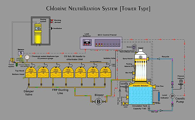
Equipment Per System:
The system consists of Hoods for covering the chlorine tonner / cylinder where chlorine gas outlet valves are fitted. The storage tank are fabricated as one piece. Highly efficient centrifugal blowers of suitable size, necessary Hoods and Ductings are provided as per the number of tonner / cylinder accounted for service. Centrifugal pumps for caustic solution re- circulation is also a part of the tonner based system.
1. FRP HOOD FOR CHLORINE TONNER / CYLINDER – FULL HOOD :
The system consists of a hood covering the complete chlorine tonner / cylinder where liquid / gas chlorine outlet valves are fitted. Hoodas are provided with 20 mm peripheral air gap for entry of fresh air during working of system.
2. FRP DUCTING :
Required quantity of FRP Ducting of size 150 MM ID is provided for leaked chlorine gas from Hoods to Centrifugal Blowers and From Blowers to absorption tank.
3. BLOWER WITH ELECTRIC MOTOR (FOR Cylinder) :
The system consists of 1 No. of highly efficient centrifugal blower of 500 M3/Hr at 800 mm WG capacity for suction of leaked chlorine from Hoods to the Absorption Tank.
4. BLOWER WITH ELECTRIC MOTOR (FOR Toner) :
The system consists of 2 Nos. of highly efficient centrifugal blower for suction of leaked chlorine from Hoods to the Absorption Tank.
5. DAMPER FOR FRP DUCTING :
01 No. FRP Dampers of size 150 mm ID is provided at discharge line of Blower and per Hoods 01 No. FRP Dampers of size 150 mm ID is provided at suction line of Blower to control the flow of Chlo – Air mixture through FRP ducting.
6. PRESSURE INDICATOR ON CAUSTIC PUMP DISCHARGE (FOR Toner) :
01 No. Pressure Indicator is provided on discharge line of Caustic Pump for indication of caustic line pressure.
7. PRESSURE INDICATOR ON BLOWER DISCHARGE :
01 No. Pressure Indicator is provided on discharge line of Blower for indication of pressure of Blower Discharge Line.
8. CAUSTIC SOLUTION TANK (For Toner) :
01 No. Caustic Tank of Capacity 8 M3 made of PP + FRP is provided for storage of 20 % conc. Caustic Solution.
The Caustic Tank consists of :
01 No. – Level Indicator of Glass Tube type for indication of level of caustic solution in the tank. Various Nozzles for inlet and outlet of caustic solution, Drain Valve with Drain Line, Overflow Line, Water Supply Inlet Line, Manhole, Vent, Diffuser etc.
9. CAUSTIC SOLUTION TANK (For Cylinder) :
01 No. Caustic Tank of Capacity 3 M3 made of PP + FRP is provided for storage of 20 % conc. Caustic Solution.
The Caustic Tank consists of :
01 No. – Level Indicator of Glass Tube type for indication of level of caustic solution in the tank. Various Nozzles for inlet and outlet of caustic solution, Drain Valve with Drain Line, Overflow Line, Water Supply Inlet Line, Manhole, Vent, Diffuser etc.
10. CAUSTIC SERVICE PIPING :
Required quantity of PP Caustic Service Piping of size 63 mm OD, 50 mm OD and 90 mm OD as per standard DIN : 8077 / 8078 is provided for re-circulation of caustic solution.
11. ‘Y’ TYPE STRAINER FOR CAUSTIC SERVICE (For Toner) :
01 No. Polypropylene ‘Y’ Type Strainer of size 2 “ is provided on Caustic Service line at suction line of Caustic Pump to avoid passage of small particles.
12. NON RETURN VALVE FOR CAUSTIC SERVICE (For Toner):
01 No. Polypropylene Non Return Valve of size 2 “ is provided on caustic service line at discharge of Caustic Pump.
13. CAUSTIC RE – CIRCULATING PUMP WITH ELECTRIC MOTOR (For Toner) :
01 No. Caustic Re-Circulating Pump of capacity 10 M3/Hr at 10 Mtr head along with suitable motor is provided on caustic solution line to re – circulate the caustic solution in to the absorption tank.
14. WATER SUPPLY PIPING FOR CAUSTIC TANK :
Required quantity of GI water supply pipe of size 1 “ to deliver water into the Caustic Tank for dilution of Conc. Caustic Solution.
The lubrication schedule is mainly required for the rotating parts of the Caustic Pumps and Blowers. The Caustic Pumps and Blowers are required to be lubricated once in three months time. Caustic Pumps shall be replenished with oil as per SAE – 30 or equivalent.
Meggar test the motor and check for direction of rotation.
Check for foreign material inside the Blower.
Check the Impeller and remove any material formed on the blades.
Rotate the Impeller by hand and see whether it is rotating freely without any friction of the sides.
When the direction etc. are checked, start the Blower.
IN THE CHLORINATION ROOM
CHLORINE GAS ABSORPTION CAPACITY = 1000 KG/HR (For Tonner)
CHLORINE GAS ABSORPTION CAPACITY = 100 KG/HR (For Cylinder)
LEAKED CHLORINE ABSORPTION SYSTEM
The system is designed to absorb leakage of chlorine leaking from one filled Toner / Cylinder in one hour time. The system is designed to absorb the chlorine gas and not liquid chlorine leaked from the Toner / Cylinder. To stop the leakage of liquid chlorine from toner is the difficult task as the liquid chlorine expands as soon as it enters into the atmosphere. Normally as soon as you find the liquid chlorine is leaking from the valve or body of the toner, you must rotate the toner in 180 degree to convert the liquid chlorine leakage into gas chlorine leakage. The chances is very less for leakage of liquid chlorine from cylinders because it is always used in vertical position.
PROCESS DESCRIPTION OF ABSORPTION SYSTEM :
The system is designed to absorb leakage of chlorine leaking from one filled Toner / Cylinder in one hour time. The system is designed to absorb the chlorine gas and not liquid chlorine leaked from the Toner / Cylinder. To stop the leakage of liquid chlorine from toner is the difficult task as the liquid chlorine expands as soon as it enters into the atmosphere. Normally as soon as you find the liquid chlorine is leaking from the valve or body of the toner, you must rotate the toner in 180 degree to convert the liquid chlorine leakage into gas chlorine leakage. The chances is very less for leakage of liquid chlorine from cylinders because it is always used in vertical position.