Construction and Function
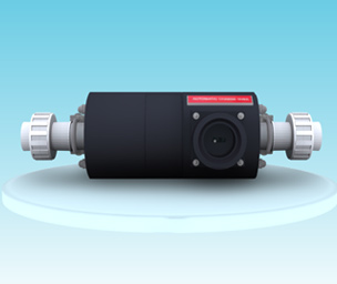 The vacuum change – over device ensures a continuous gas supply for gas dosing systems by changing the gas supply over in time from the empty supply battery to stand by battery.
The vacuum change – over device is operable without auxiliary power. From which battery the gas is supplied, is indicated visually but as the option the change over position can also be remote indicated 2 reed contact.
As soon as the vacuum rises to a value of about 3-4 m ws/ 78”-118” wc, which can be caused by an empty or closed supply battery, the change over function is triggered.
The change – over device can be used in connection with the chlorine dosing units C 105 and V 107 or V 115.
NOTE: If the chlorine gas dosing units are retrofitted with the change – over device, a compensation for the main regulator has to be provided.
| Technical Data | |
|---|---|
| Medium | CL2,SO2 |
| Maximum flow rate | 10 kg/h CL2,SO2 500 PPD CL2,SO2 |
| Minimum flow rate | >= 50 g/h CL2,SO2 >= 2.5 PPD CL2,SO2 |
| Optional connections |
PE – tube 8 X 11 PE- tube 10 X 4 PVC – pipe DN 10 PE – tube ½” od. PE – tube 3/8” od. |
| Materials | PVC / viton / FEP / glass silver / hastelloy C |
| Weight | IP 65 / IP 67 |
| Area Of Operation | about 2 kg |
1.1 Electrical Data
| For option with 2 reed contacts for remote indication | |
| Supply voltage | max. 75 V DC / 50 V AC |
| Power Consumption | 1 A |
| Wattage | max. 50 W |
Installation
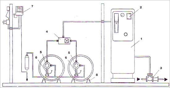
Connect the vacuum change – over device at the inlet side to two vacuum regulators and at the outlet side to the chlorine gas dosing unit. The inlet connections for the vacuum regulators are marked with the inscriptions IN I and IN II, the connection for the chlorine dosing unit with OUT.
The vacuum lines between the vacuum regulators and the change – over device should be kept as short as possible and should not exceed a maximum length of 6 m. Thus a minimum pressure loss can be ensured.
A pre-condition for trouble – free functioning of the vacuum change – over device is the tightness of all lines and connection.
see 3.1 /3.2 Leak test
The vacuum change – over device should be installed as depicted in figure 1 on the following page.
2.1 Empty Remote indicator
To indicate the level of the supply battery electrically, it is possible to equip the change – over device with a empty remote indicator that can be mounted directly onto the standard indication body. The vacuum change – over device can also be retrofitted with this remote indicator. The remote indication is achieved via a magnet and 2 reed contacts operating as make contact.
sectional drawing of the remote indicator.
Commissioning
After having completed the insatallation continue ommissioning the change - over device.
Warning : There device must be commissioned only by qualified personnel strictly complying with the instruction for handling the hazardous substance chlorine. The qualified staff must wear protective clothing and gas mask when doing the work described in the following.
Note : Prior to the initial starting all parts carrying chlorine gas have to checked for leaks.
3.1 Leak Test of the vacuum Side
Close the connecting valves of the drums or cylinders.
Start the injector. There upon the vacuum lines are evacuated and in this operating state the change – over device switch uncontrollably.
After about 10 minutes the Rota meter must not indicate a flow.
If Rota meter yet indicate the flow, the complete dosing system must be checked for possible leak.
Warning : as pre condition for the leak test the chlorine gas dosing unit must be evacuated and free of chlorine gas and the injector be in operation.
To check the single component of the dosing system, disconnect the vacuum line between the vacuum regulator and the Rota meter one after another and close them tight with the finger.
If the Rota meter stops indicating a flow after having disconnected one of the vacuum lines, the leak has to be at the disconnected components.
3.1 Leak Test of the vacuum Side
Stop the injector.
Open the connecting valves of the drums or cylinders by about one revolution.
Check the connecting parts and inlet valves of the vacuum regulators for leak by mean of ammonia close by the relevant parts and squeezing a little bit of the ammonia gas out of the bottle. If there is chlorine gas escaping anywhere, white vapor develops.
Warning : Even the slightest detected leaks have to be removed immediately.
3.3 First Commissioning
After the leak test terminated successfully, the vacuum change – over device can be commissioned.
Entirely open the connecting valve of the drums or cylinder.
Start the injector. There after chlorine gas is dosed. The position of the indicator pin of the chnge – over device signals from which battery the chlorine gas is supplied.
3.3 First Commissioning
Open all cylinders of drums and start the injector.
Close the supply battery that is in Operation.
The change – over device switches the gas supply over to the stand by battery after a short period of time (that depends on the dosing quantity and the length of the line)
Then check, if the changing over from the stand by battery to the former supply battery function, as well.
Open again all cylinder or drums. The vacuum change – over device is now ready for operation.