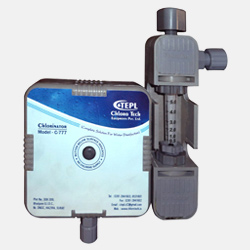
The Model No. C-777 is a high Quality low cost chlorinator of the solution feed, vacuum type. Proven design, rugged construction and use of best available materials assured precise gas feeding, low maintenance, dependable operation and long life. The chlorinator mounts directly on the cylinder valve by means of yoke clamp connection. Ejector is designed for low pressure operation and may be mounted directly in the pipe line.
The C-777 chlorinator is available with single or multiple metering tubes for feeding chlorine to one or more points of application, single and dual tubes may be mounted directly on the front of the chlorinator regulator or remote from it.
Remote metering tubes are mounted on a plastic coated bracket which can be located adjacent to or remote from the regulator.
Each metering tube is supplied with its own ejector and rate valve and operates independently of the others.
The Model C-777 is available for manual or start-stop operation. Maximum feed rates range from 100 grams to 5000 grams/hr.
Design Features
COMPLETE SAFETY
Vacuum operation assures safety for plant operating personnel and equipment. Built in safety features prevent damage to chlorinator under abnormal operating conditions.
ECONOMY
Low initial cost, multiple metering tubes, simplicity of installation and maintenance, rugged corrosion resistant construction contribute to the most ecumenical chlorination system.
FLEXIBILITY
Optional multiple metering tubes and ejectors provide complete flexibility for applications requiring chlorination at two or more points.
MINIMUM MAINTENANCE
Pipeline mounting of ejector eliminates the need of solution hose. Simplicity of design minimizes routine inspection and maintenance time.
Operation
The chlorine gas from the cylinder enters the chlorinator where it is filtered to remove any foreign material which might be present. Water flowing through the ejector creates a vacuum which opens the inlet valve to admit the gas into the regulator. The spring opposed diaphragm regulates the vacuum at this point to a closely controlled value.
The gas passes through the flow meter(s) and the rate control valve and then to the ejector or ejectors where it is thoroughly mixed and dissolved in the water and carried to the application point as a solution. When multiple metering tubes and ejectors are used, each operates independently of the others. Adjustment of one of the gas flow rates has no effects on other rates.
The system is completely under vacuum from the ejector to the gas inlet valve during operation. If the water supply to the ejector is stopped, or the operating vacuum is lost for any other reason,. The spring loaded gas inlet valve immediately closes to isolate the chlorinator from the gas supply. Any gas, under pressure which might enter the regulator is vented from the system through the built-in pressure relief valve. If the source of chlorine gas is exhausted or the gas line plugged an excess vacuum valve in the regulator closes to prevent any moisture being pulled back into the regulator or the gas supply lines. At the same time the red signal indicator pops out or the bottom of the regulator to indicate that the gas supply has been interrupted.
The ejector is provided with a diaphragm operated back check valve to insure that water does not leak back into the regulator when the system is shut down. The ejector is designed for mounting directly in the pipeline if desired.
Engineering Specifications
CAPACITIES
Standard metering tubes are available with the following maximum capacities: 0.5, 1, 2, 3, 4, 5 (Kg. per Hr) of chlorine gas. Any combination of capacities may be used on multiple metering tube units as long as the total does not exceed 120 kg. PD.
FLOWMETER RANGEABILTY
20 to 1 for any one metering tube. For example, a chlorinator with a maximum capacity of 25 Kg. PD. Can measure and control gas feed over the from 1.5 to 25 kg. PD. Metering tube scale length is 4 inches for easy readability.
CONECTIONS
Ejector Water Inlet – ¾ - inch NPTE standard, Size is determined by water flow required to operate chlorinator.
Safely Vent – 3/8 inch tubing
MOUNTING
The chlorinator mounts directly on the valve of a 50 or 75 kg. Chlorine cylinder by means of a yoke clamp connection.
CONTROL MODES
Manual adjustment of the rate valve alters feed rate. On multiple meter chlorinators each meter chlorinators each meter is equipped with a rate valve. Start-stop control is obtained by installation of an automatic valve in the ejector supply line. This valve, controlled by a timer. Flow, pressure of pump control device, will start or stop the chlorinator.
OUT OF GAS INDICATOR
A manually reset visual indicator signals when the chlorine gas supply is exhausted or interrupted.
MATERIALS OF CONSTRUCTION
Kerstin, PVC, tantalum, Vinton silver plated Hastelloy Alloy C. Teflon, Kel-F, silver and extra heavy duty borosilicate glass are used in the construction of the chlorinator and used in the construction of the chlorinator and ejector.
ACCURACY
Accuracy is within + 4% of set feed rate.
EJECTOR REQUIREMENTS
The following curves depict the required operating conditions for the ejectors used with the Series 777 chlorinates. The Standard Ejector will satisfy most job requirements and should be used whenever possible. The High Capacity and Low Capacity Ejectors should be used when it is necessary to meet conditions the Standard Ejector can not be met with these ejectors contact the factory.
SHIPPING WEIGHT
Approximately 9 kgs. Including standard accessories.